While i was exploring the tutorials of arduino i stepped on
Fritzing. Fritzing is a program which makes the creation of pcb from breadboard a piece of cake. If it could solder the parts also, then you wouldn't need to do anything. In this part of the guide i'll introduce you to fritzing and the next post will be about the developing and etching of the pcb itself.
In a few words, you install fritzing, place the parts on the breadboard of fritzing and you got your mask for pcb and the schematic of the circuit for easy transfer to Orcad or same programs.
 |
| starting screen (2) |
You can get fritzing from
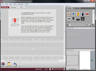
here. Run it, and you see the screen on your left (img. 2) where you can see an empty breadboard waiting you to place parts. The only thing you have to do is place the parts you do want and everything else is done automatically.
On the top right there is the parts' list fritzing has from the beginning. For start it's ok, but you can add more parts ( i'll discuss that in another post).
Just below the parts' list is the "Inspector" which helps you change the attributes of each part. The last window shows the schematic and the pcb of the circuit you are designing on the breadboard. You can make also modifications but this will not be the subject of this post.
Steps in a hurry:
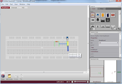
- Choose what parts you do need form the list, and place them one by one with drag and drop on the breadboard.
- Change their attributes from the "Inspector" window.
- Connect two pins with each other by clicking on the one and then drag the mouse until the other pin. The wires don't connect if you cross them.
 |
| setting up the breadboard (3) |
 |
| breadboard ready (4) |
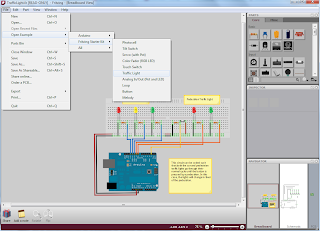
Suppose we have already transfer our circuit at fritzing's breadboard. We just want to get the mask in order to make the pcb. Below i have used an example from fritzing the "Traffic Light" which is an arduino dependable (img. 4).
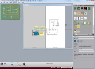
Now choose the pcb view from the "Navigator" on the bottom of the window. You can see that our pcb is ready and it's also on the dimensions of the arduino just like a shield.
Notice that when you select a part on the breadboard it is also selected in all views (pcb and schematic).
 |
| pcb view- ready to export mask (5) |
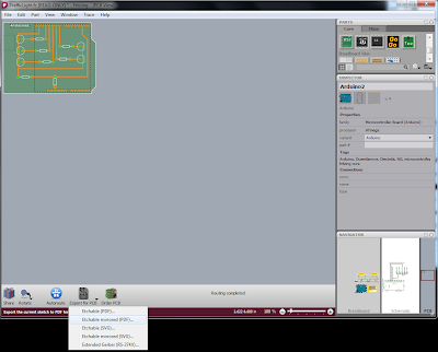
The only thing we have to do is export the mask to pdf and print it.
So: While we are at pcb-view, select the "Export for PCB" icon and pick an option from the list. Select between pdf or svg format and mirrored or not (img. 6). Otherwise you can go from
File -> Export ->for Production. The process is about the photo-resisting method of pcb creation.
 |
| exporting the mask (6) |
That's all for now. I want to try to integrate fritzing with OrCAD or some other circuit analysis program because fritzing also gives the schematic from a breadboard. At last the process of etching and developing will be the next on the blog.


